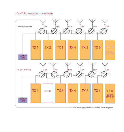
"6+1" Active system transmitters


This system is composed of “N” transmitters connected to the antenna and 1 transmitter used as back-up unit that is connected to the dummy load.In case one of the “N” transmitters fails it is immediately replaced with the back-up unit and the faulty unit is switched to the dummy load.
This system is composed of “N” transmitters connected to the antenna and 1 transmitter used as back-up unit that is connected to the dummy load.In case one of the “N” transmitters fails it is immediately replaced with the back-up unit and the faulty unit is switched to the dummy load.
The basic operations in a N+1 back-up system is identical to the 1+1 system plus those functions that are typical of this system:
• the power alarm is detected
• it activates both Interlocks on the faulty transmitter and on the backup unit
• it controls the coaxial relay transferring the faulty TX on the dummy load and the back-up TX on the antenna
• it sets the same frequency of the faulty transmitter on the back-up unit
• it switches the audio matrix from the faulty transmitter to the back-up unit
• it switches the RDS matrix
• it switches the interlock matrix in order to release the interlock of the load on the TX connected to the load and the interlock of the combiner on the back-up unit
• it turns on the back-up unit
Other functions are:
• Local/Remote
• Normal/Automatic
• parameter management
• timing management
• interface among the telemetry systems
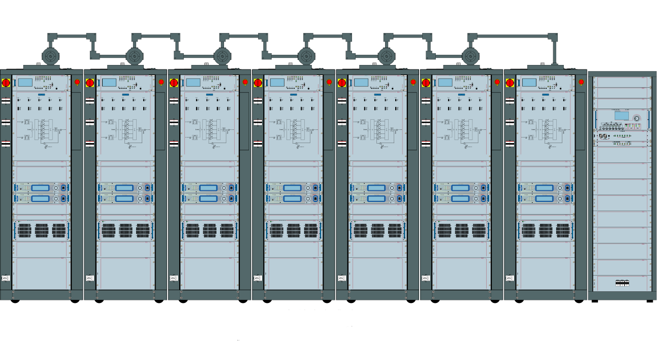
The image of this layout is purely demonstrative and may change without notice. The configuration is only referred to installed equipment; rack, cover panels and all others accessories are to be defined at order.


